AHEAD 2015-2019
Web page: LARIX Facility
Description of the infrastructure
The LARIX (LARge Italian X-ray facility) laboratory is located in the Scientific-Technological Pole of the University of Ferrara in an underground building that includes a 100 m long tunnel with two large
experimental rooms on each side. It hosts two hard X-ray installations, the 12 m long LARIX-A located in the experimental room A, and the 50 m long gamma-ray facility, LARIX-T, installed in the tunnel. LARIX A is ideal for performing linearity tests of hard X-ray detectors (e.g., Zavattini et al. 1997, NIM A 401, 206), for reflectivity measurements of X-ray reflector samples (e.g., Frontera et al. 1991, SPIE Procs. 1549, 113, Frontera et al. 2008, SPIE Procs. 7011, 52) and to perform ground calibration of entire hard X-ray experiments (e.g., Loffredo et al. 2003, A&A 411, L239–L242, about JEM-X calibration for INTEGRAL satellite). LARIX-T is suitable for testing gamma-ray reflectors (e.g., crystals) and low-weight gamma-ray detector prototypes. The normal manned operating hours of the test facilities are 08:00 to 19:00 Monday to Friday. It will not normally be possible for visitors to access the test facility out of these hours. It is not possible to control the facility using a remote connection, all measurement sequences have to be set up via local access. For additional informations please visit the LARIX web site.
Installation 1: LARIX-A
Installation 2: LARIX-T
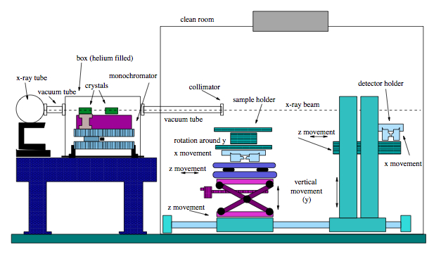
LARIX-A can be operated from about 10 keV to 140 keV. its main components are described below.
X-ray Sources Two X–ray tubes, with different operational voltage, are mounted onto an optical table and powered by independent high voltage supplies. One tube is equipped with a Molybdenum anode, operating from 20 to 60 kV and current from 10 to 60 mA (Maximum operational power: 3.6 kW). The spot size is 0.5 x 0.5 mm2. The other tube is equipped with a Tungsten anode, operating from 40 to 140 kV and current from 0.1 to 5 mA (Maximum operational power: 70 W). The minimum spot size is 0.5 x 0.5 mm2. The output window of the first tube is equivalent to a 0.3 mm thick Beryllium foil, while that of the second tube is equivalent to a 1.5 mm thick aluminium foil. By means of remote controlled manipulators, both tubes can be moved up and down and translated along a direction perpendicular to the X–ray beam. Both X–ray tubes plus their translation stages are contained in a box made of a 5 mm thick Pb layer.
Collimators and filters A set of two collimators limits the divergence of the X–ray beam. Filters are available for selecting the band of interest and related fluorescence lines. Filters include different thickness high purity Copper and Aluminium tails.
The Monochromator system The polychromatic source spectrum can be monochromatized with a double crystal diffractometer (Bragg-Bragg configuration) (see Figure) providing a fixed-exit beam independently of the selected photon energy. The monochromator is installed inside a sealed plexiglass box, where helium can be pumped. The box X–ray entrance and exit windows are made of polyethylene terephthalate (PET) 0.075 mm thick with a very high transparency at the operation energies. The output X–ray beam travels in evacuated tubes (10-3 mbar) up to the sample to be tested.
Sample holder and Manipulators The sample to be tested is positioned on a pedestal equipped with manipulators that allow to move the sample in three perpendicular directions (X,Y,Z) and rotate it around the vertical and the horizontal axes. An angular position accuracy of 3” can be achieved with a repeatability of 1”.
X-ray detectors The available detectors include: 1) a large area (30 cm diameter) CsI X-ray imager, with pixel size of 300 µm; 2) a Nitrogen cooled spectrometer of high purity HPGe with a surface area of about 78 cm2, a thickness of 13 mm and an X–ray entrance window of 0.254 mm Beryllium foil; 3) a NaI(Tl) scintillator detector of 42×42 mm2 and 3 mm thickness, with imaging (a few mm) and spectral (resolution of 25% at 60 keV) capabilities. The detector holder can be moved in three perpendicular axes (X,Y,Z) and is equipped with a rotation stage (3.6” resolution) around the vertical.
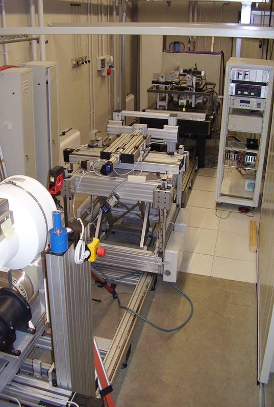
Other features and remote console Both the sample and detector pedestals can be translated along the X-ray beam direction on 6 m long rails. An overhead travelling crane (1000 kg weight–bearing, 20 m long) is installed parallel to the rails. A clean room of 100.000 class of 12 meters square hosts the sample; it can host also the detector when the distance between sample and detector is less than 2 m. The sample holder, the detector holder and the holder of the position gauge of the sample holder, can be moved on 10 m long rails as shown in Fig. 2. The control room, equipped with a PC-based interface running under LabView, is separated from LARIX A by means of a wall 2.1 m high, made of Al+Pb. It is possible to locate the X–ray beam, measuring its energy resolution.
LARIX-T is installed in the 100 m tunnel with a controlled access. Its operational energy range is from 60 keV to 1 MeV. Safety doors separate the tunnel from the experimental room A where the console room is located. In Figure below it is shown a sketch of the installed facility in the current configuration. Its main components are described below.
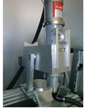
Gamma-ray source A portable betatron (Vmax = 2.5 MV, Pmax = 310 W) or an gamma-ray generator (Vmax = 320 Volts, Pmax = 1800 W) are available. The gamma-ray generator is equipped with a tube with a Tungsten anode (fine focus of 0.3 mm diameter). For the current application (Laue lens development), the source adopted is the X-ray tube (see Fig. 2.2, left panel). A 20 mm thick Tungsten plate with a 3 mm diameter hole, followed by a 50 mm thick Lead shield with a 1 mm diameter hole limit the beam divergence (Fig. 2.2, right). Either source can be translated in the plane Y-Z (X being the beam axis), and rotated around the Z and Y-axes.
Beamline The photons coming from the gamma-ray source through the initial collimator enter (X-ray entrance and exit windows of carbon fiber 3 mm thick) into a 21 m long beam-line under vacuum (of ≤1 mbar) of stainless steel with an internal diameter of 60 cm. The beamline is planned to be extended up to 70 m.
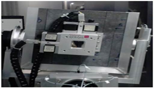
Final slit collimator A final slit collimator (see Fig. 2.3 left), mounted on a pedestal, can be translated in the Y-Z plane and rotated around the X, Y and Z axes, to get a gamma-ray pencil beam always parallel to itself and to a given direction. The slit aperture can be varied by means of four crossed and independent 20 mm thick blades of Tungsten Carbide.
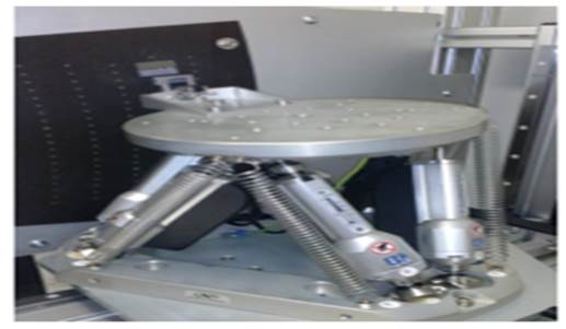
Sample carriage and holder The sample to be tested is placed on a holder, that can be coarsely translated in the (X,Y) plane, and finely positioned and oriented by means of a 6-axis hexapod system. The hexapod allows uncertainties in the sample orientation of 1 arcsec and in the sample translation of 1 µm. A view of the hexapod is shown in Fig. 2.3 (right).
Detector system It includes two detectors (a gamma-ray imager and a solid-state spectrometer) placed on a carriage that can move back and forth on a 15 m long rail along the X-axis. The carriage allows also the translation of the detectors in the Y-Z plane with an uncertainties of 0.5 mm in each direction. The gamma-ray imaging detector (CsI(Tl) scintillator viewed from an array of photodiodes) has a useful area 20 x 20 cm2, with a spatial resolution 200 µm. The gamma-ray spectrometer is a cooled HPGe detector with 2.5 cm diameter with an energy resolution about 500 eV at 122 keV.
Clean room The final slit collimator, along with the sample holder, are located in a clean room (class better than 105, US FED STD 209E Cleanroom Standards) endowed with a thermal and hygrometric control (temperature within 1 C, relative humidity = 60% within 10%).
Gamma-ray beam monitor The beam intensity at the exit of the beamline is monitored using a calibrated NaI(Tl) scintillator integrated with a photomultiplier tube.
Console room All movements, except the detector translation along the gamma-ray beam direction, are motorized and remotely controlled, by a LabVIEW software interface. A selection of light indicators makes the X-ray beam (source and collimator slit) and hexapod/sample holder automatically moving to the desired position.