BEaTriX, Merate, Lecco, Italy
BEaTriX (Beam Expander Testing X-ray facility) is a laboratory present at INAF-Osservatorio Astronomico Brera in its premises of Merate. It is a unique pathfinder facility characterized by a broad (170 × 60 mm2), uniform and parallel X-ray beam (divergence ∼ 2 arcsec HEW) at the energy of 4.51 keV, highly monochromatic (FWHM = 30-50 eV). A second beam line is going to be added at the energy of 1.49 keV.
The system is very compact (9 × 18 m2), positioned on a stable foundation (gray in Figure 1) designed and built to isolate the beam line from vibrations. The facility works at a vacuum level of 10-3 mbar, easily evacuated in a short time. The vacuum pumping system is entirely based on magnetic turbo pumps, and oil-free pre-vacuum and backing pumps, to avoid optics contamination. The small size of the facility also contributes to reduce the evacuation time with respect to bigger X-ray facilities. Moreover, the modular compartments design, guaranties that the vacuum can be broken independently in the different sectors, enabling to replace the optics under test in a short time: simulations have shown that the experimental chamber (F in Figure 1) can be evacuated in about 30min. The experimental chamber opens into an ISO5 clean tent, to allow samples to be loaded and unloaded in a clean environment. Venting is performed in all the system with dried dehumidified air. A thermal box is also present therein (Figure 3), to radiatively heat the X-ray optics under test, at temperature ranging from -10 to +50 °C; some gradients can also be applied. A software based on the NI Labview platform allows all the BEaTriX operations.
BEaTriX prime goal is to prove that it is possible to perform the acceptance tests (PSF and Aeff) of the ATHENA Silicon Pore Optics (SPO) Mirror Modules (MM) at the production rate of 3 MM/day. Nevertheless, the facility can also be used to test other X-ray optics: the limit in size is 365 × 365 × 600 mm, given by the thermal box structure; the limit in weight is 5kg, interfacing structure included (for the SPO case, the interface is 2.6 kg), given by the hexapod maximum load (see later).
 |
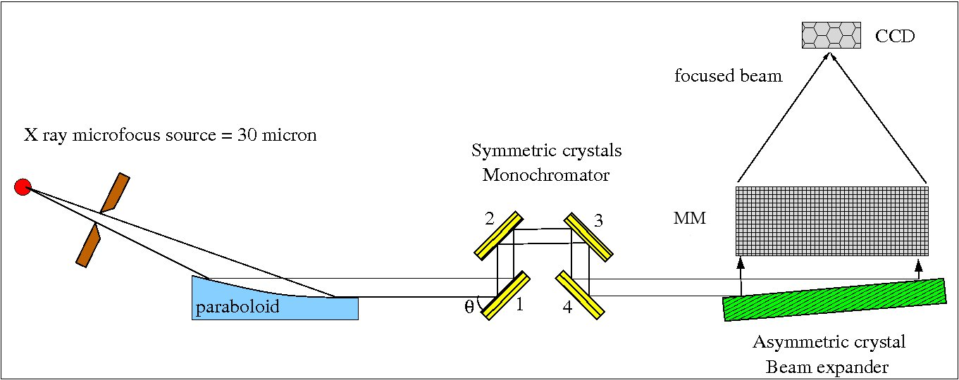 |
Figure 1. Left: the mechanical design of the facility in the laboratory. Right: the optical design
The source is a micro-focused X-ray emitter (A) with focal spot size of 35 µm × 35 µm. The 4.51 keV line is emitted by a Ti anode. The source is in UHV environment, separated by a 100 µm thick Be window. It can be aligned with mechanical adjustments in air. The flux of the Ti source was measured to be 6 × 10¹¹ ph/sec/sterad.
The beam is propagated through the short arm (B) onto the Optical Chamber (rectangular tank in Figure 1), where the optical components for the beam moderation are present. The parabolic mirror (C) is used for beam collimation; diffraction on 4 symmetrically cut crystals (D) have the function to monochromate the beam, while the asymmetrically cut crystal (E) expand the beam and reflect it at about 90 deg. The emerging beam has then a size of 170 mm in the horizontal direction and 60 mm in the vertical direction.
An Si-PIN detector (Amptek, X123 with 25mm2 area / 500 µm thickness / 25 µm Be window) in present in front of the last crystal to monitor the flux and the alignment stability (Fig. 2 right).
The monochromation system (D) can optimize either the horizontal divergence or the flux. Two different configurations can be adopted one in which the vertical divergence only is optimized (max flux), and one in which both vertical and horizontal divergences play a key role and need to be optimized. This is obtained with a rotation of the second CCC (yellow motor in Fig. 2 left). The performance of BEaTriX in the two different configurations were simulated as follows, with the experimental results well in line with the expectations:
-
High flux – low collimation (CCC aligned at max flux)
-
flux = 60 ph/s/cm2
-
collimation: HEWver = 1.46 arcsec, HEWhor = 2.44 arcsec
-
-
Low flux – high collimation (second CCC rotated by about 10 arcsec from the position of max flux)
-
flux = 10 ph/s/cm2
-
collimation: HEWver = 1.46 arcsec, HEWhor = 4.78 arcsec
-
 |
 |
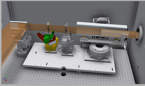
Figure 2. Design (left) and picture (right) of the components inside the Optical Chamber. From right: the paraboloidal mirror, the two CCCs in charge of the monochromation, the BE crystal. The Beam Monitor is visible in front of the BE.
 |
 |
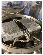 |
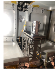
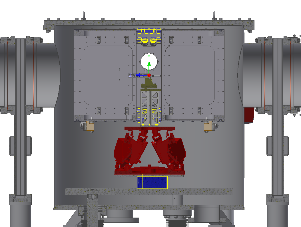
Figure 3. Left: MM mounted on its supporting structure, connected to the hexapod. Centre: design of the MM Chamber, showing the thermal box (grey), the MM supporting structure in titanium (brown), the lightened beam in stainless-steel (grey), the hexapod (red) and the linear stage (blue). Right: top view of the thermal box inside the MM Chamber, with the top cover removed for the installation of the thermal box.
The focused beam is propagated through the long arm (G) into the detector (H), placed at 12 m distance. The detector is a directly illuminated CCD with sensor size of 27.6 mm × 27.6 mm and pixel 13.5 mm. It is connected to the long arm, and motorized in air for movements in the vertical (range = 1500 mm) and horizontal (range = 150 mm) directions. A focal range of 500 mm is obtained also with in air motorization and a properly designed bellow in front of the CCD. The long arm is made of 6 tubes to leave the possibility to modify in the future the focal length of the facility: major setup changes will be necessary but in principle focal distances other than 12 m are possible (fstd = 12000 ± 250 mm; fpossible-1 = 10295 ± 250 mm; fpossible-2 = 8295 ± 250 mm).
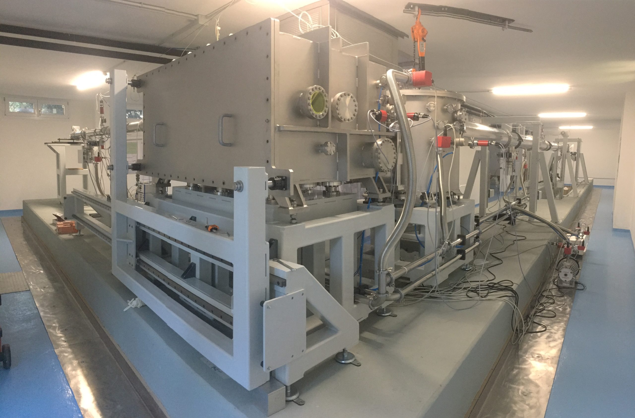
Figure 4: A picture of the BEATriX facility in the INAF/Osservatorio of Brera premise
In the MM chamber (cylindrical tank in Figure 1, and Figure 3), the beam encounters the MM (F), and it is thereby focused. The MM is motorized in vacuum, in order to be aligned to the beam: a hexapod, with max load of 5kg, is used to this purpose (red in Figure 3 center). The hexapod is mounted on a translational stage (blue in Figure 3 center), used to move the MM out from the beam, for the direct beam measurements. The MMs are installed, by means of 6 Neodymium magnets, on a titanium interface made by 3 parts, that can be adjusted to adapt to the width of the different MMs. A thermal box (internal size: 350 mm × 350 mm × 600 mm) is also present to radiatively cool/heat the X-ray optics under test, in the temperature range T=293±25K. Two of the radiating panels are removable, giving accessibility to the MM and enabling possible temperature gradients of the MM in X and Y.
The beam focused by the MM is propagated through the long arm (G) into the detector (H), placed at 12 m distance. The detector is a directly illuminated CCD with sensor size of 27.6 mm × 27.6 mm and pixel 13.5 m. It is connected to the long arm, and motorized in air for movements in the vertical (range = 1500 mm) and horizontal (range = 150 mm) directions. A focal range of 500 mm is obtained also with in air motorization and a properly designed bellow in front of the CCD. The long arm is made of 6 tubes to leave the possibility to modify in the future the focal length of the facility: major setup changes will be necessary but in principle focal distances other than 12 m are possible (fstd = 12000 ± 250 mm; fpossible-1 = 10295 ± 250 mm; fpossible-2 = 8295 ± 250 mm).
Reference papers :
- Basso S., Salmaso B., Spiga D. et al., First light of BEaTriX, the new testing facility for the modular X-ray optics of the ATHENA mission (2022), arXiv e-prints, arXiv:2206.15468
- Salmaso, B., et al. BEaTriX, the Beam Expander Testing X-ray facility for testing ATHENAs SPO modules: progress in the realisation, Proc. SPIE 11119, 111190N (2019) https://doi.org/10.1117/12.2530430
- Basso, S., et al. Thermal simulations for characterization of ATHENA Mirror Modules with a radiating box in the BEaTriX facility, Proc. SPIE 111191, 111191I (2019) https://doi.org/10.1117/12.2530622
- Spiga, D., et al. Optical simulations for the laboratory-based, expanded and collimated X-ray beam facility BEaTriX, Proc. SPIE 11110, 111100E (2019) https://doi.org/10.1117/12.2530066